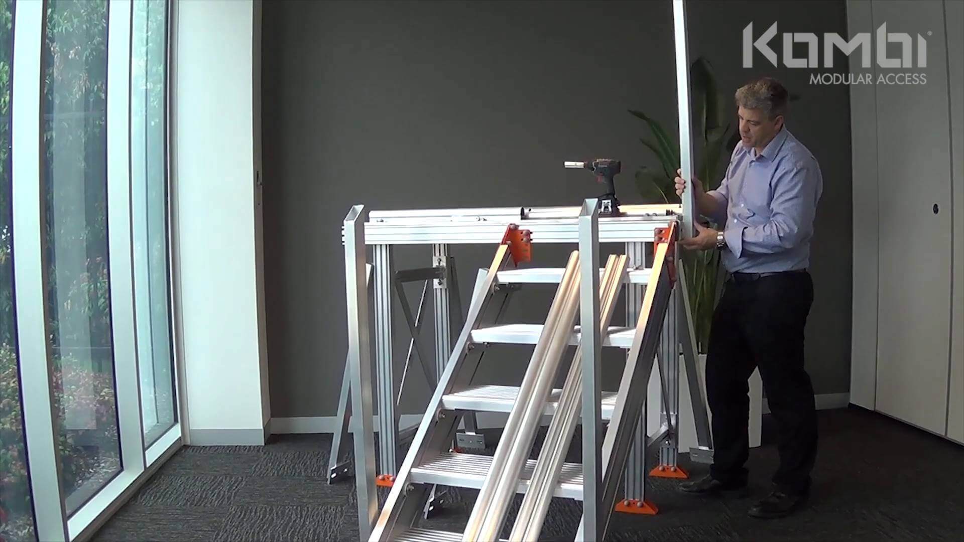
KOMBI® Design Purpose
- For use by construction workers, specialist trades and maintenance personnel.
- Suited to provide access to equipment in many sectors such as HVAC, industry & manufacturing, lift & elevator machinery, railway plants and stations, site sheds and solar and renewable energy farms.
KOMBI® Builda Configurator

- A cloud based 3D design tool, the KOMBI Builda created specifically to configure KOMBI systems.
- Includes KOMBI proprietary design parameters.
- Provides 3D model and front, top and side views and list of components required to build the system.
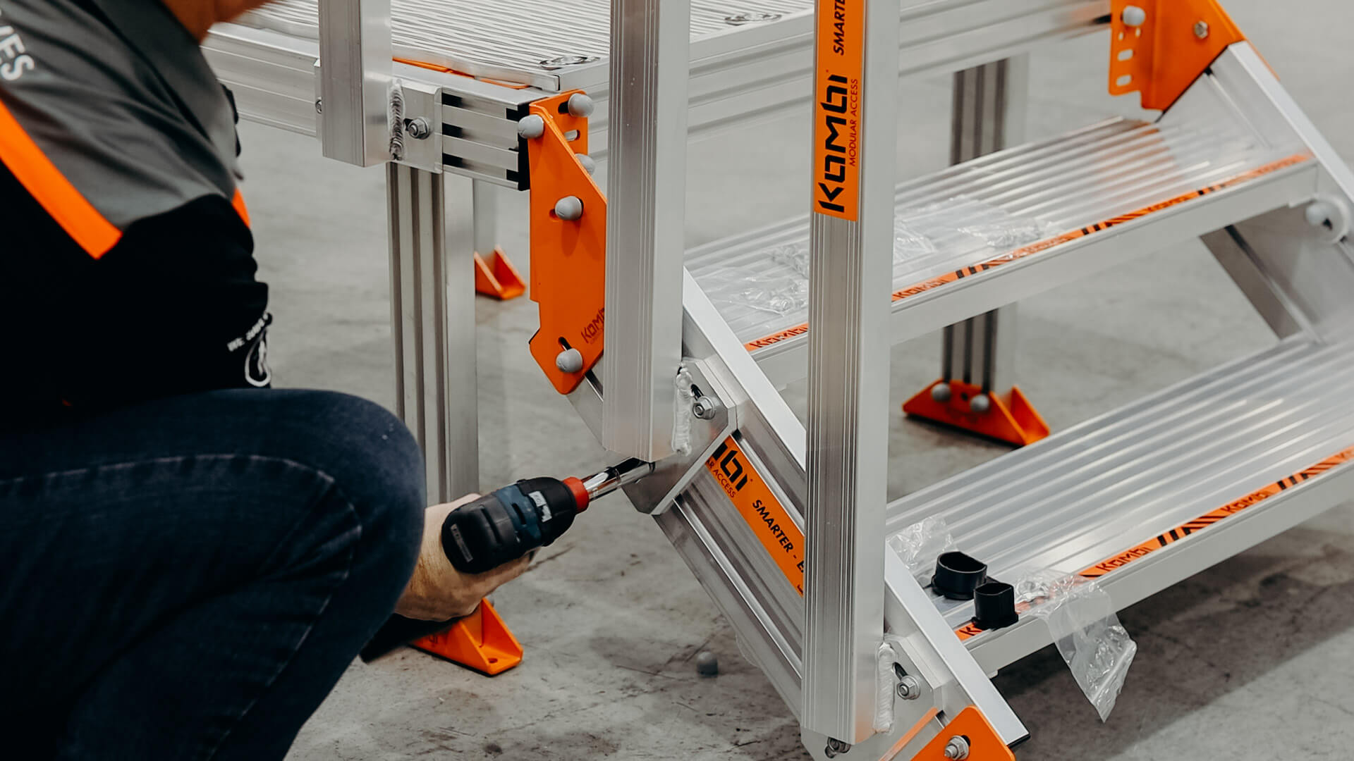
KOMBI® Proprietary System
- KOMBI is an Australian made, engineered and configured system.
- A series of live load testing and calculated parameters have determined design outcomes - read the Technical Statement.
For Design Assistance
Melbourne Office
 1029 Mountain Highway,
Boronia VIC 3155
Australia
View in google maps 1300 072 651
 info@kombiaccess.com
- REQUEST A QUOTE


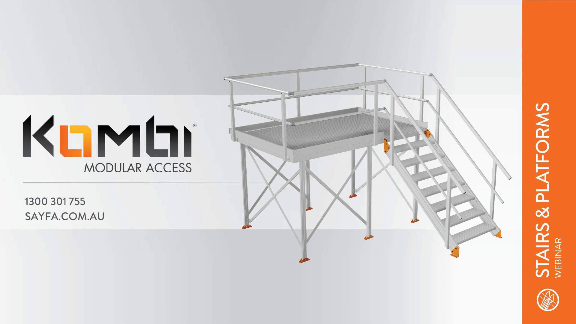
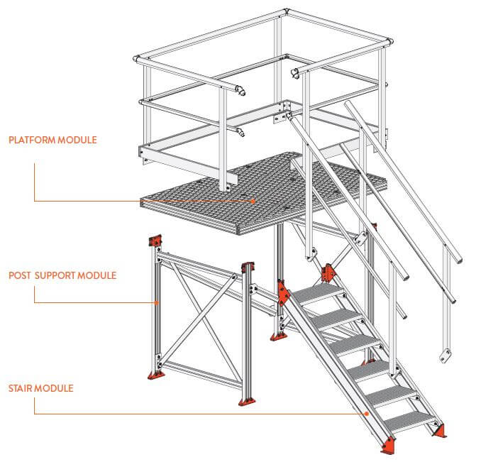
KOMBI® is made up of 3 primary modules
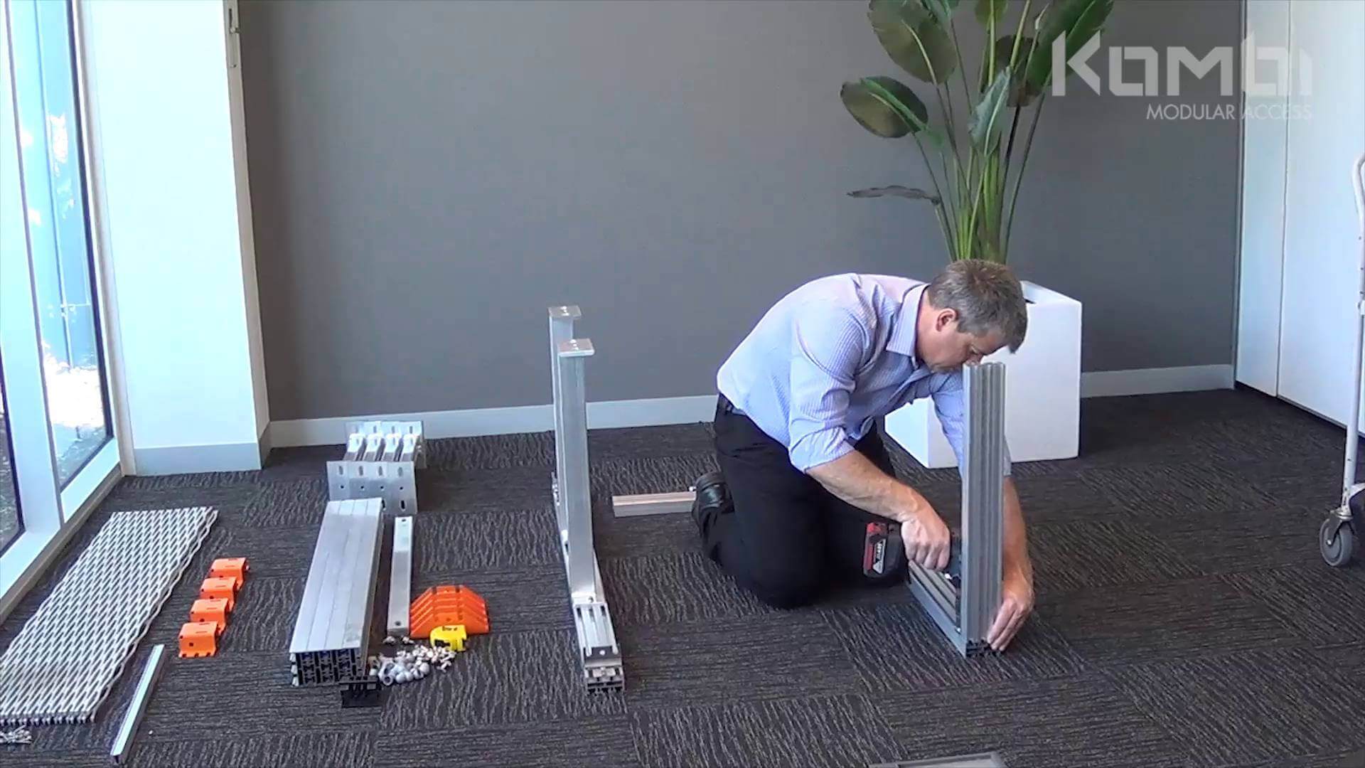
- Post support module: assembled first
- Platform module: assembled second
- Stair module: assembled third
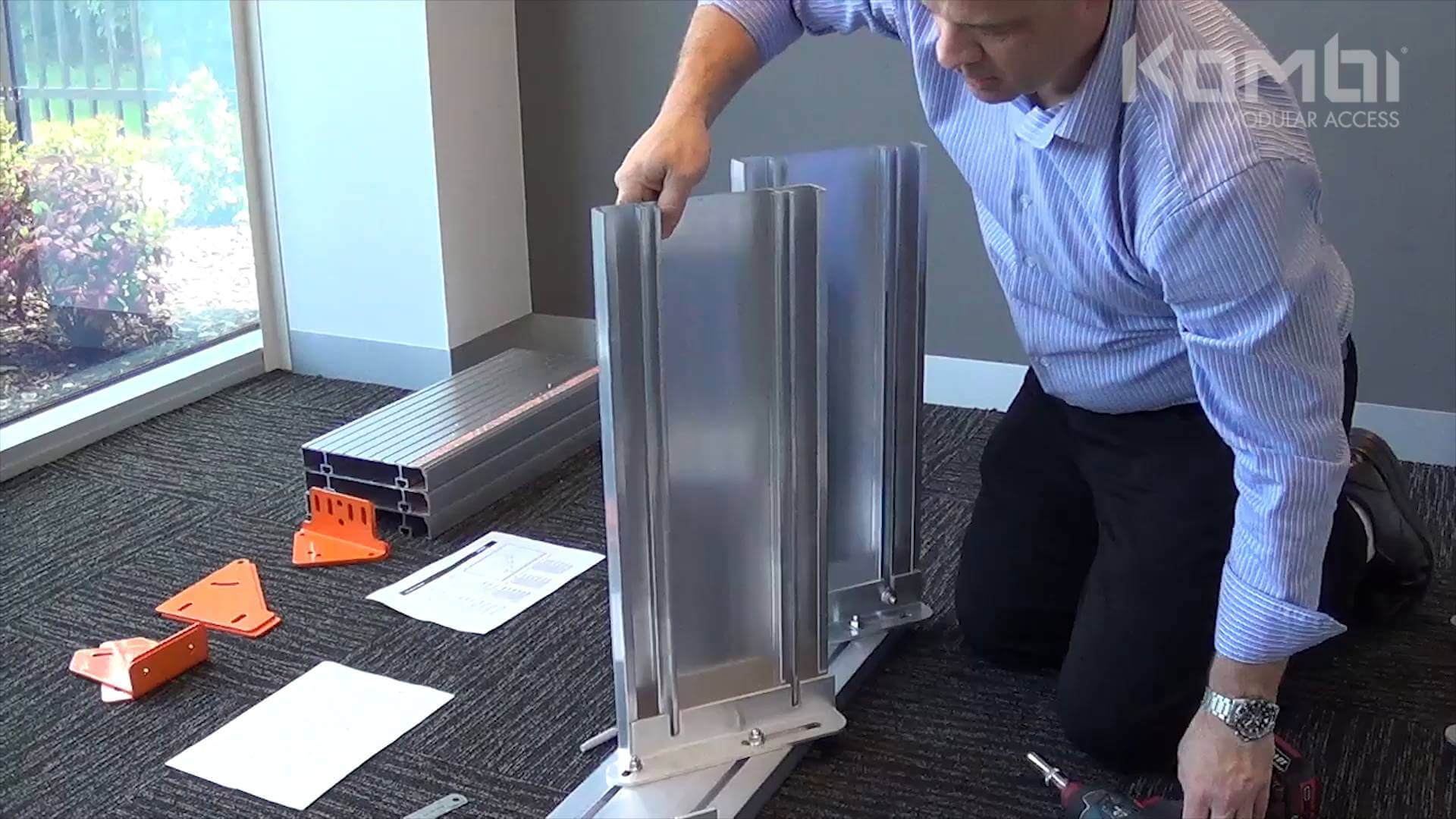
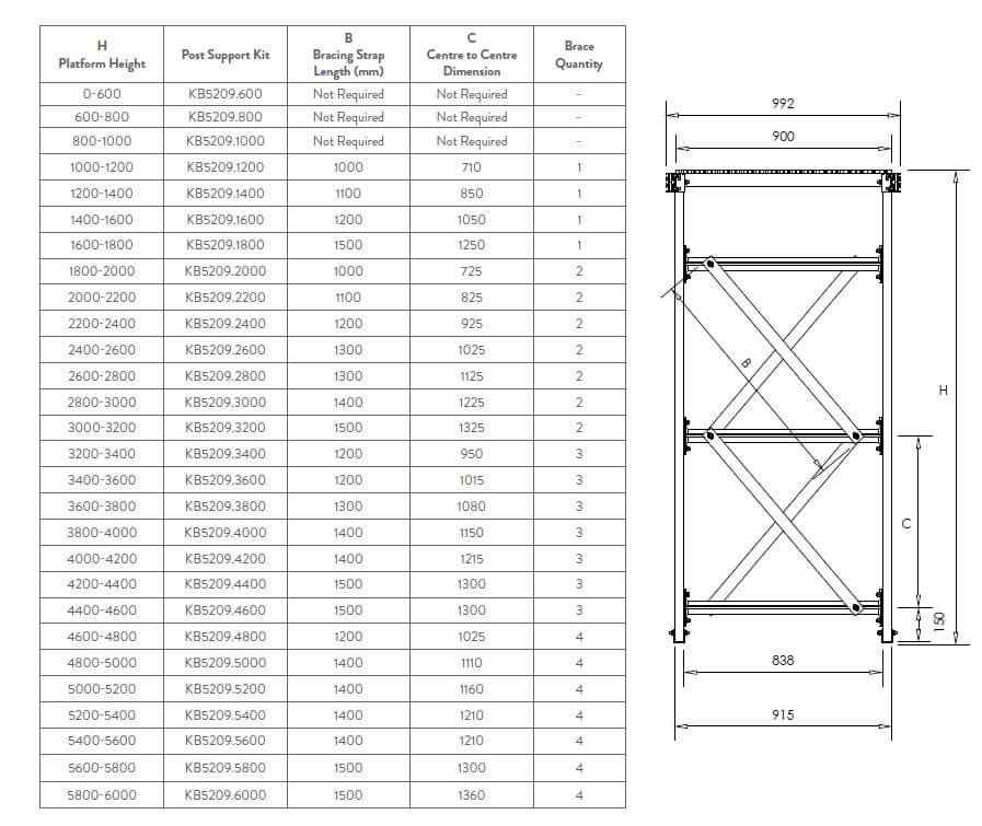
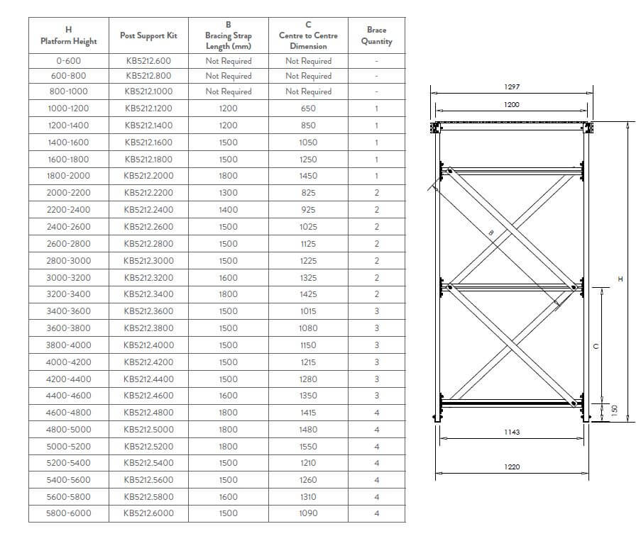
POST SUPPORT ASSEMBLY
- KOMBI post support structure is design to support a live load of 2.5kPa (250kg/m2).
- KOMBI supports are available in three standard widths 610mm, 915mm and 1220mm. Custom widths can be manufactured.
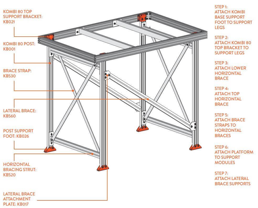
Installation Requirements
- See configuration tables for set out of horizontal braces, bracing straps and lateral braces.
- Lower horizontal brace struct KB520 is set at 150mm above bottom of post.
PLATFORM ASSEMBLY
- KOMBI Platforms are designed to support a live load of 2.5kPa (250kg/m2 distributed load).
- KOMBI Platforms are available in three standard external width dimensions 687mm, 992mm and 1297mm. Custom widths can be manufactured.
- KOMBI Platforms can be joined together to create larger decks where required.
- For dead loads such as an aircon unit, pallets etc please consult with the SAYFA design team to confirm correct configuration.
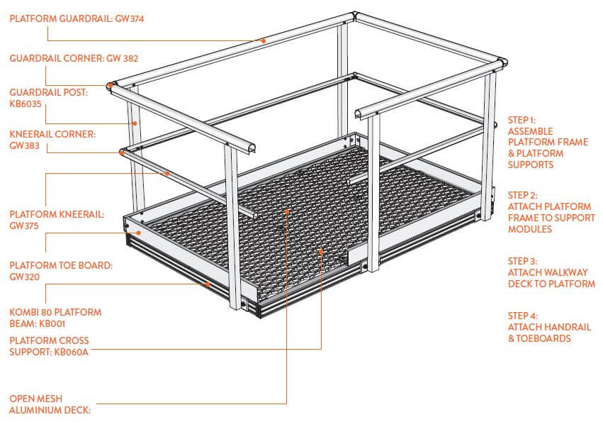
Installation Requirements
- Platform mesh aperture to be a maximum of 15mm where persons have access to or work beneath the platform. The GW334 narrow width deck to be used in this application.
- Guardrail posts to be space dat a maximum of 2000mm centres.
- Maximum dimensions between underside of handrail to top of kneerail is 450mm.
- Platform toe board is required where an object could fall from the platform onto an area to which access by persons is a possibility. Maximum gap between toe board and deck is 10mm.
STAIR ASSEMBLY
- KOMBI Stairs are designed to support a load of 2.5kPa live load (250kg/m2).
- KOMBI Stairs are designed to best suit a 40 degree angle however are suitable angles from 25 - 45 degrees.
- KOMBI Stairs are available in three standard widths: 610mm, 915mm & 1220mm. Custom widths can be manufactured.
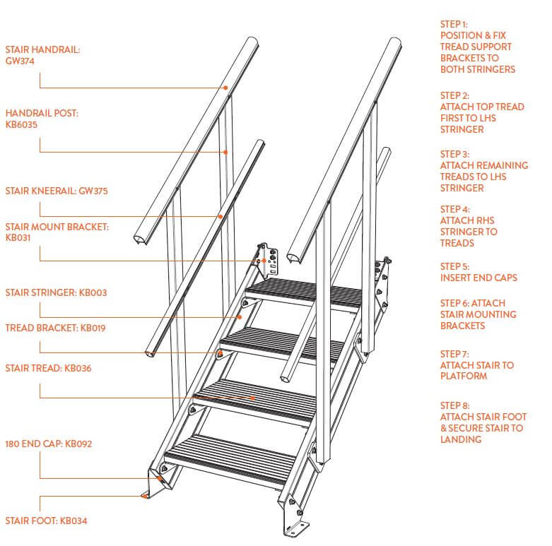
Installation Requirements
- Minimum inside distance between stair stringers to be not less than 600mm.
- Clear space between handrails/kneerails to be no less than 550mm.
- The number of treads in a flight must not be less than 2 or greater than 17.
- Treads are allowed maximum of 5mm variation in spacing as per AS1657:2018.
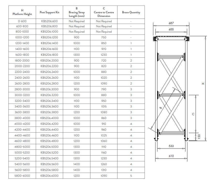
Instructions For Layout
- Step 1: Identify correct post height.
- Step 2: Determine correct post support kit.
- Step 3: Assemble post support bracing as per tables below.
900 Series Bracing Layout
1200 Series Bracing Layout
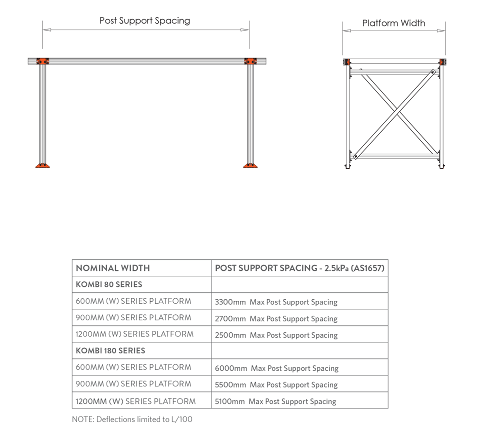
Post Support Spacing Information
- KOMBI Platforms are designed to support a live load of 2.5kPa (250kg/m2).
- Calculations assume maximum flooring mass of 12kg/m2 (weight of guardrail and aluminium deck).
- Allowance for floor vibration has not been taken into account in design.
- Platform deflection has been based on two variables, frequent access (less deflection) and infrequent access (greater deflection). Table below shows post spacings based on above.
- Lateral bracing is required as per configuration tables.
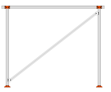
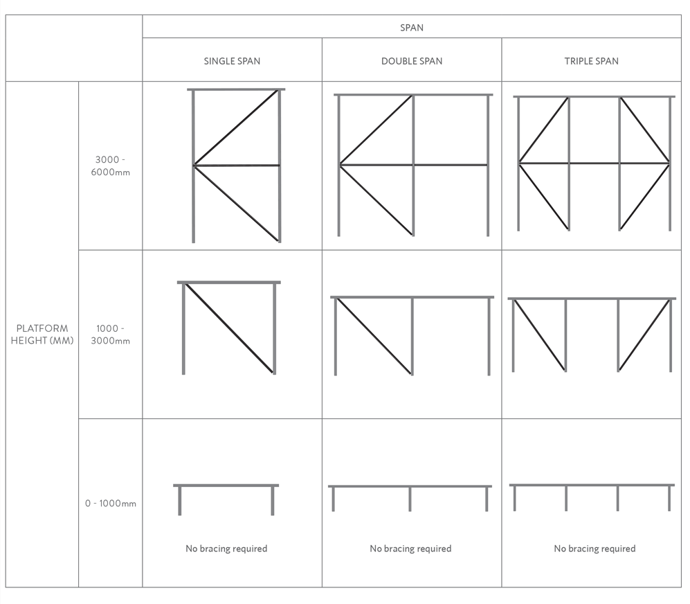
 Lateral Brace Installation
 Lateral Brace Installation
- KOMBI Platform proprietary design allows freestanding platforms of up to 6000mm.
- Platforms above 3000mm require a horizontal brace mid span of the post in all bays.
- For longer platforms exceeding triple span, up to 30m, lateral bracing is require in the first and last bay only.
- For longer platforms from 30m - 50m, lateral bracing is required in the first, centre and last bay only.
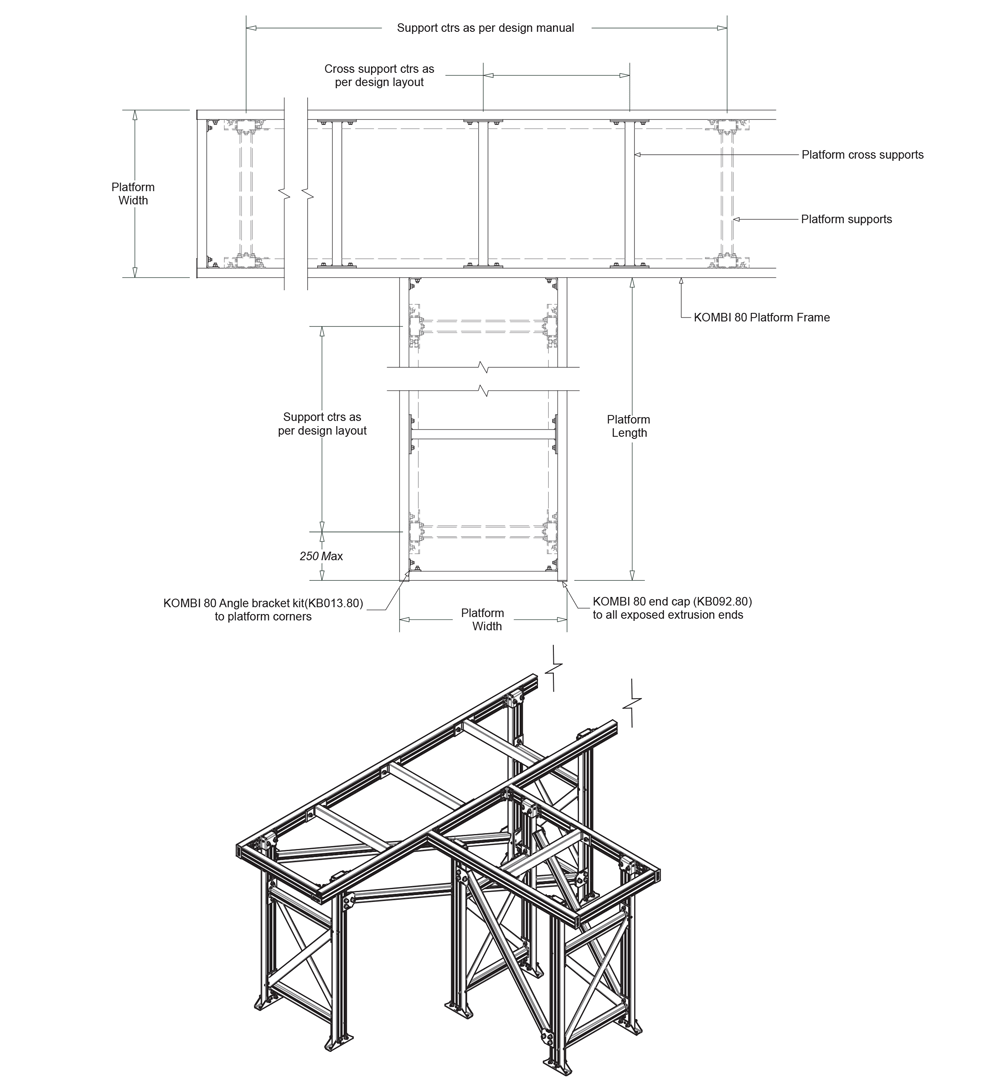
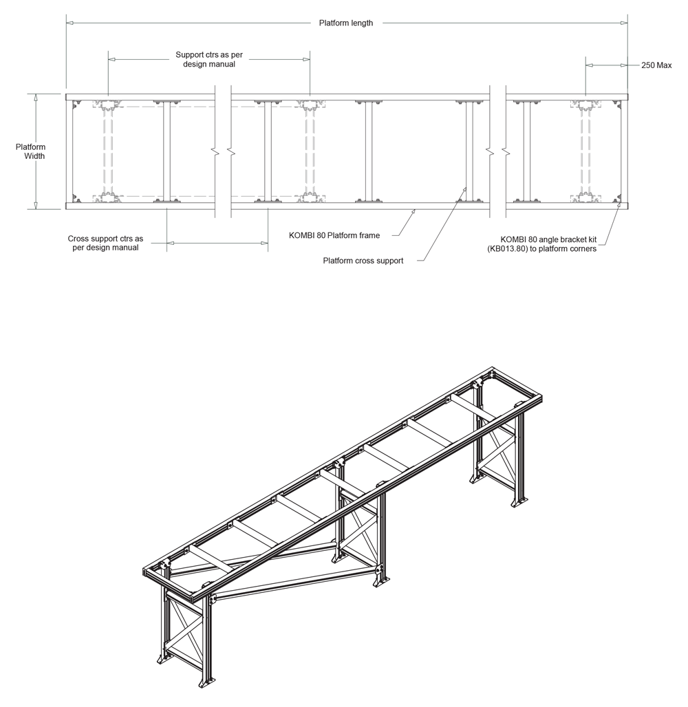
Platform Set Out Guidelines
- Platform cross supports positioned at 600mm centres.
- Post supports positioned as close to end of platform as possible. (250mm max from outside edge of platform to centre of post.)
Platform Set Out Guidelines
- Platform cross supports positioned at 600mm centres.
- Post supports positioned as close to end of platform as possible. (250mm max from outside edge of platform to centre of post.)
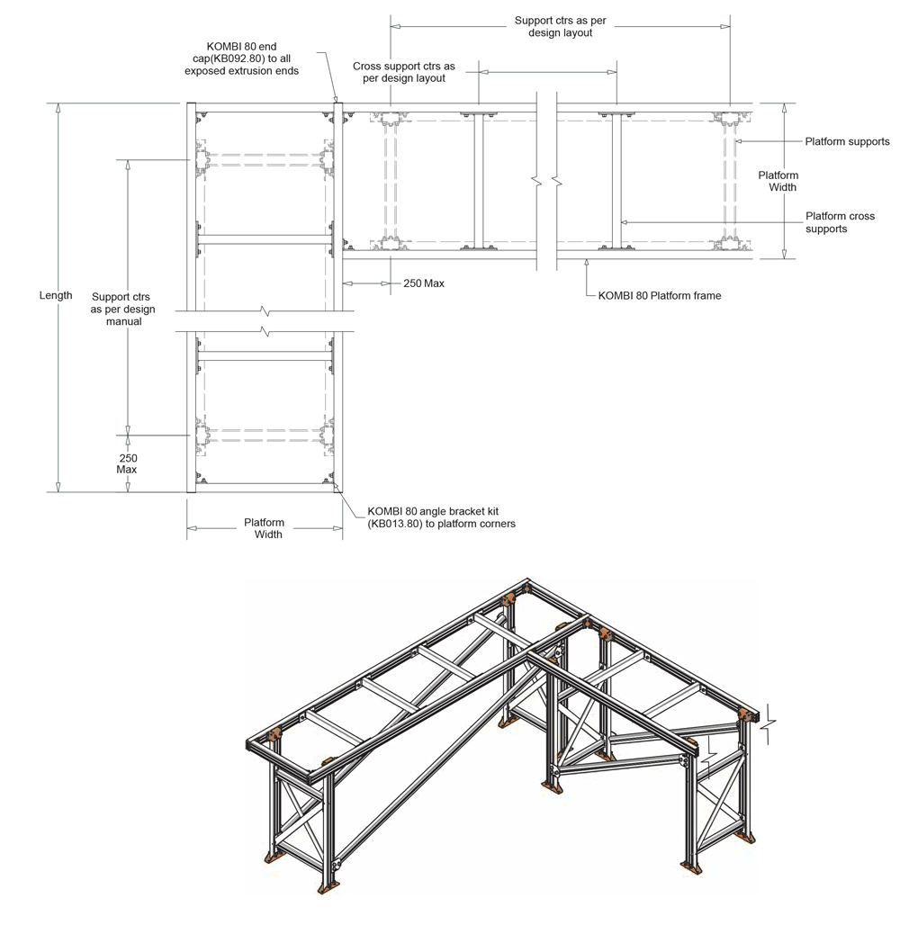
Platform Set Out Guidelines
- Platform cross supports positioned at 600mm centres.
- Post supports positioned as close to end of platform as possible. (250mm max from outside edge of platform to centre of post.)