| CRITERIA | DATA | NOTES |
| ALUMINIUM EXTRUSION | | |
| KOMBI 180 | Aluminium Grade 6005A-T5 | |
| KOMBI 80 | Aluminium Grade 6005A-T5 | |
| KOMBI 60 | Aluminium Grade 6106-T6 | |
| Bracing Straps | Aluminium Grade 6106-T6 | |
| Walkway Mesh | Aluminium Grade 6106-T6 | |
| Handrail | Aluminium Grade 6106-T6 | |
| Kneerail | Aluminium Grade 6106-T6 | |
| Toe Board | Aluminium Grade 6106-T6 | |
| Stainless Steel Brackets | Stainless Steel Grade 316 | |
| Aluminium Brackets | Aluminium Grade 5083-T5 | |
| PLATFORM LOADINGS | | |
| Live Load | 2.5kPa | In accordance with AS 1657:2018 |
| Concentrated Loading | 1.1kN | Applied through 100 x 100 pad at any point |
| Mesh Slip Rating | R11 | |
| Max Free Standing Height | 6000mm | Subject to Sayfa technical advice |
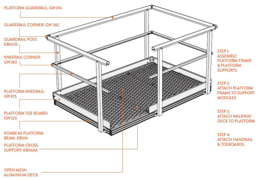
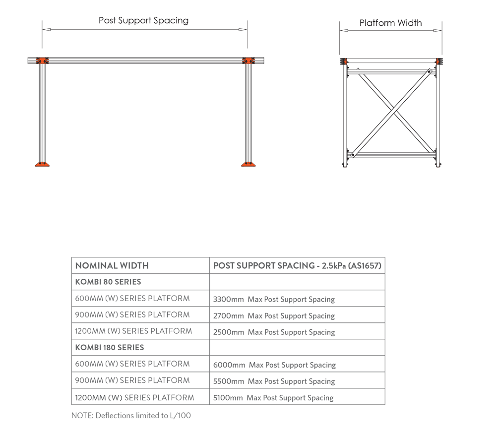
| Platform Support Spans | KOMBI 80 SERIES | Deflection limited to the span length divided by 100 |
| 600 Series (W) Platform - 3300mm max spacing | |
| 900 Series (W) Platform - 2700mm max spacing | |
| 1200 Series (W) Platform - 2500mm max spacing | |
| KOMBI 180 SERIES | |
| 600 Series (W) Platform - 6000mm max spacing | |
| 900 Series (W) Platform - 5500mm max spacing | |
| 1200 Series (W) Platform - 5100mm max spacing | |
| Platform Mesh Openings | Personnel access under platform | Where personnel is required to access underneath platform narrow mesh (GW334) must be used. |
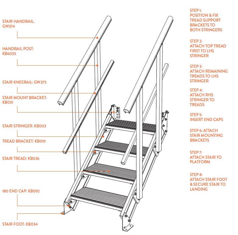
| STAIR LOADINGS | | |
| Live Load | 2.5kPa | Applied to tread and landing |
| Deflection | L/100 or 40mm | Whichever is the lesser |
| Tread Loadings | 2.2kN per lineal metre or a concentrated loading of 1.5kN | In accordance with AS 1657:2018, Section 7.1.1 |
| Max Stair Treads | 17 treads, 18 risers | In accordance with AS 1657:2018 |
| Stair Widths | Max 1500mm wide | |
| Stair Angles | 26 degrees to 44 degrees | Ideal angle is 40 degrees. Angle can be increased to reduce footprint. |
| Stair Risers | Riser - 130 ≤ R ≤ 225 | All risers and goings in the same flight of stairs shall be uniform dimensions within a tolerance of ± 5mm |
| Going - 215 ≤ G ≤ 255 | |
| Combination = 540 ≤ (2R + G) ≤ 225 | |
| DESIGN WIND CRITERIA | | |
| Region | A1 | |
| Regional Gust Wind Speed | V100 = 41m/s | |
| Terrain Category | 2 | |
| Topographical Multiplier | MT = 1.0 | |
| Terrain/Height Multiplier | Mzcat = 0.96 | |
| Shielding Factor | MS = 1.0 | |
| FASTENERS | | |
| Material | Stainless Steel 316 | |
| KOMBI T-Bolt Fixing | M10 x 25mm, 316 SS | |
| KOMBI Nut Torque | 60nM | |
| HANDRAIL | | |
| Platform Guardrail Post Spacing | 2000mm Max | |
| Max Handrail Height | 1000mm | Typically 987mm standard from deck to top of handrail |
| Kneerail Height Below Top Rail | 450mm from top of kneerail to underside of kneerail | |
| Platform Toe Board | Use KOMBI GW320 | Required if an object could fall from a platform or landing onto an area to which access by persons is available. |
| Limitations of Use | Not suitable for BCA / NCC stair design. | |
| DISSIMILAR METALS | | |
| Aluminium to Concrete | To be painted with a bitumen paint. | |
| Aluminium to Roof Deck | Shall be separated with EPDM tape. | |
| Aluminium to Stainless Steel | Brackets to be powder coated or EPDM separated. | Note: This does not apply to fasteners. Ref AS/NZS 1664.1:1997 Section 5.1. |
| WEIGHT | | |
| Walkway Mesh 13mm x 600mm Wide | 6.5kg / m2 | |
| KOMBI 80 Extrusion | Approx 2.8kg / m | |
| KOMBI 180 Extrusion | Approx 4.2kg / m | |
| KOMBI Platform including Walkway Mesh | Approx 18kg / m2 Excluding Handrails | This is an approximate weight only. Depending on different combinations this can vary. |


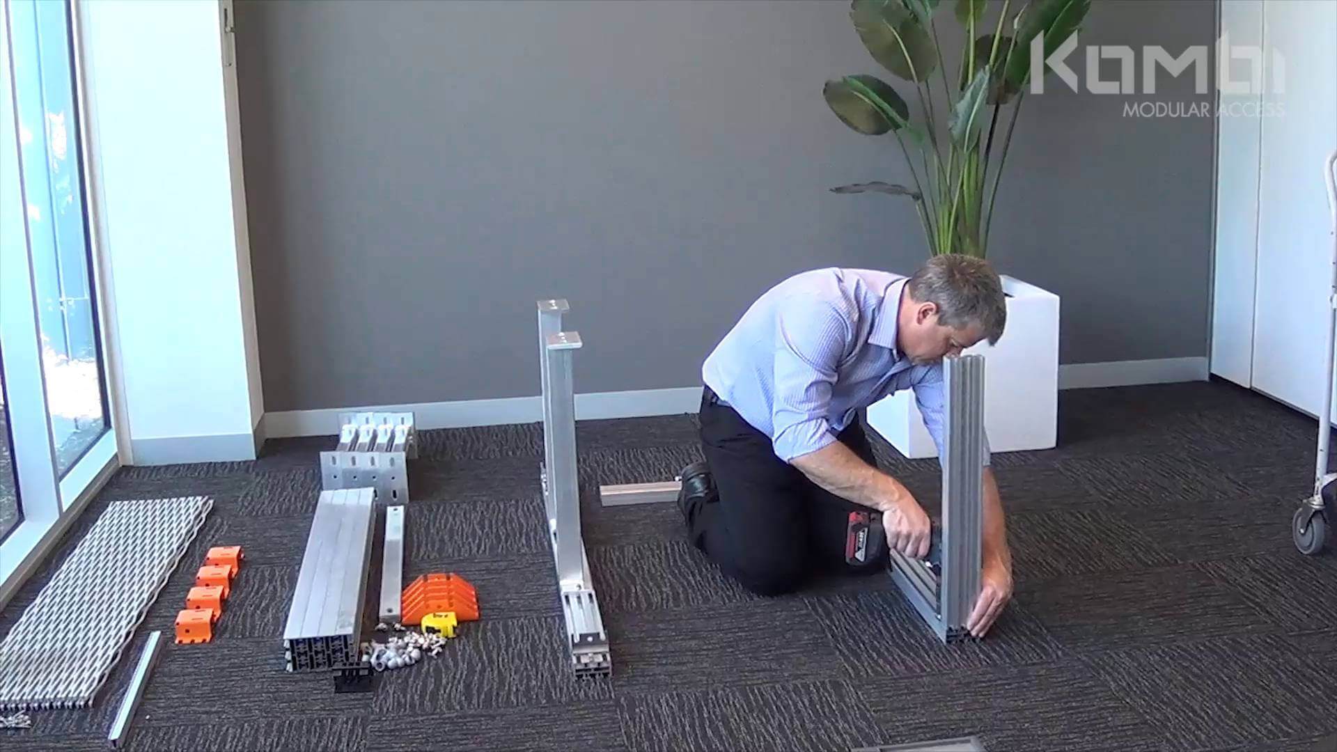
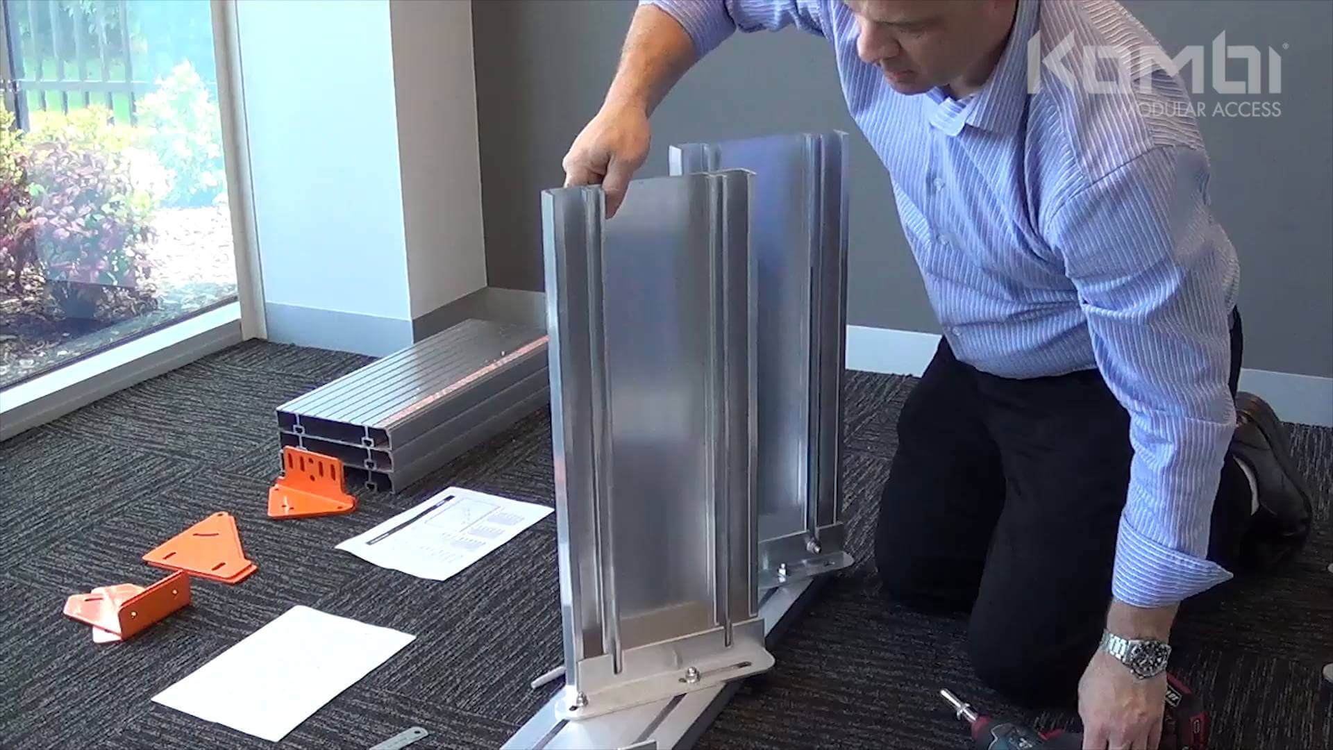
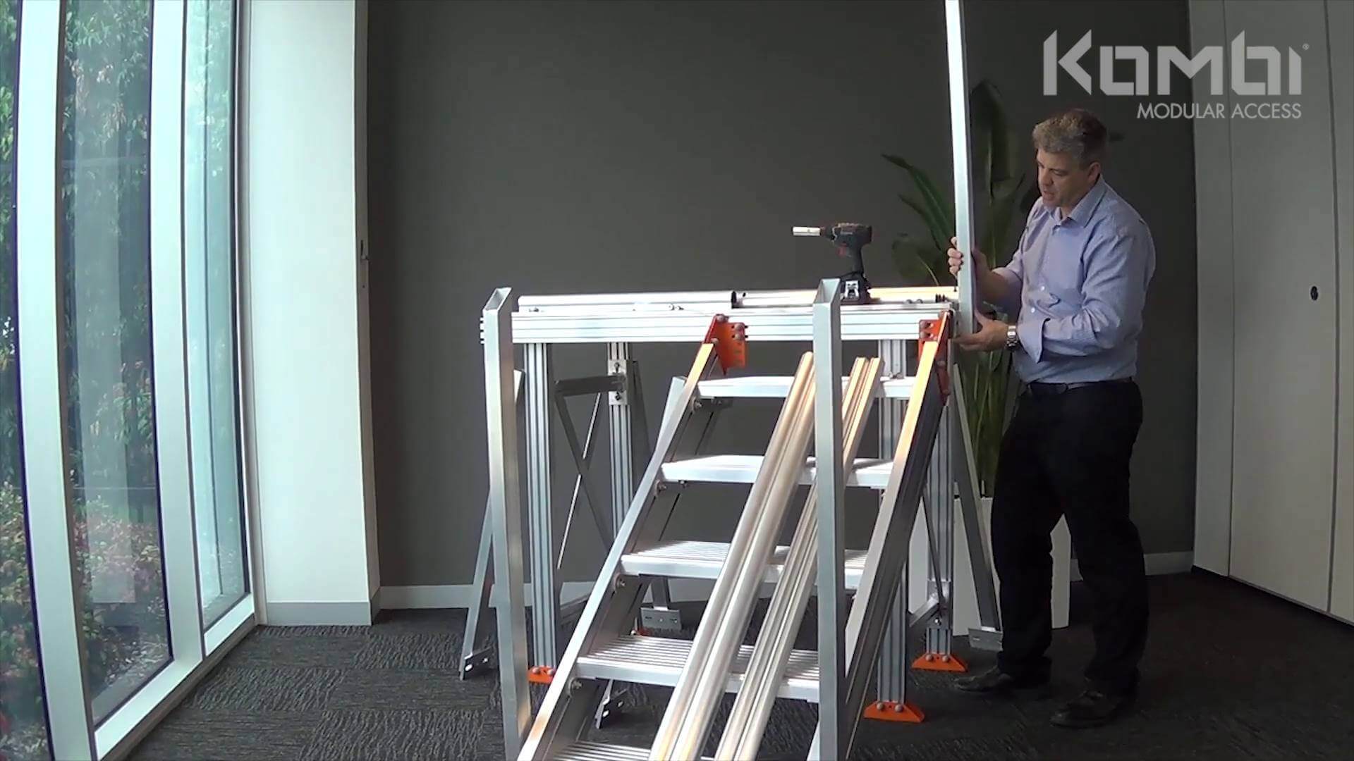
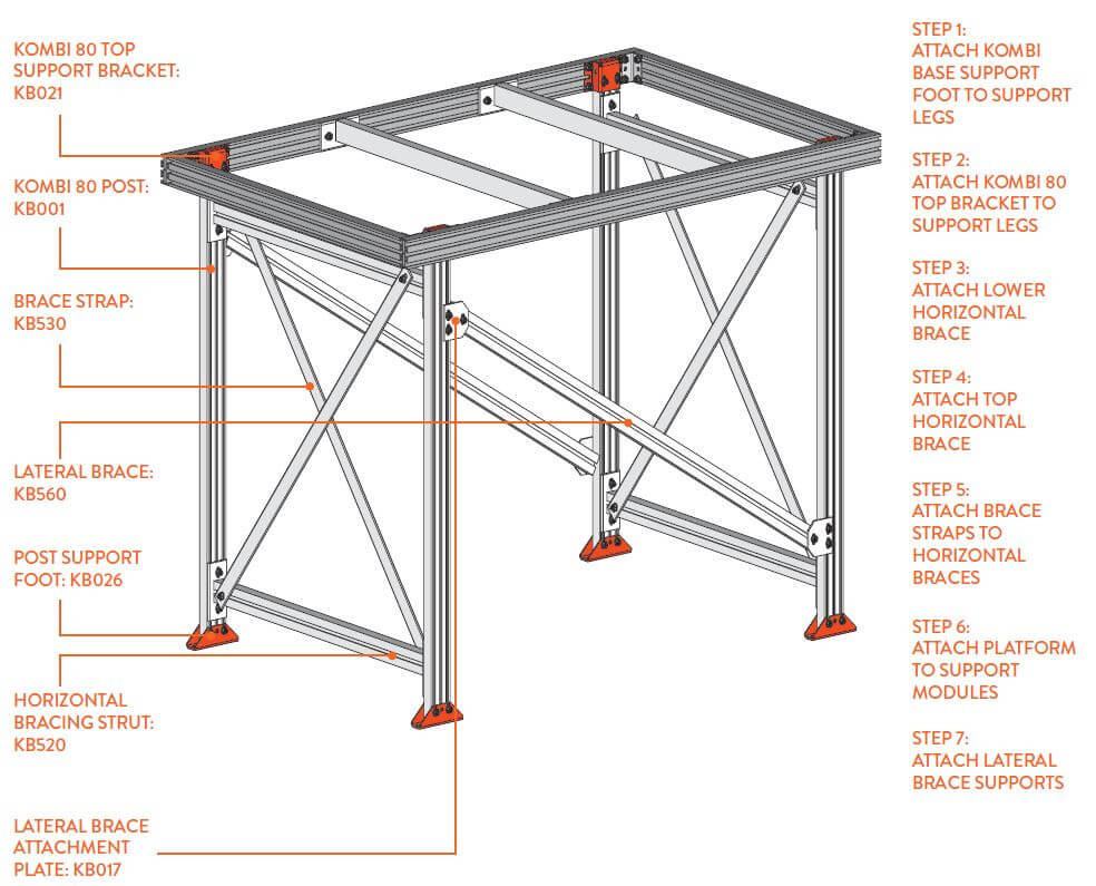


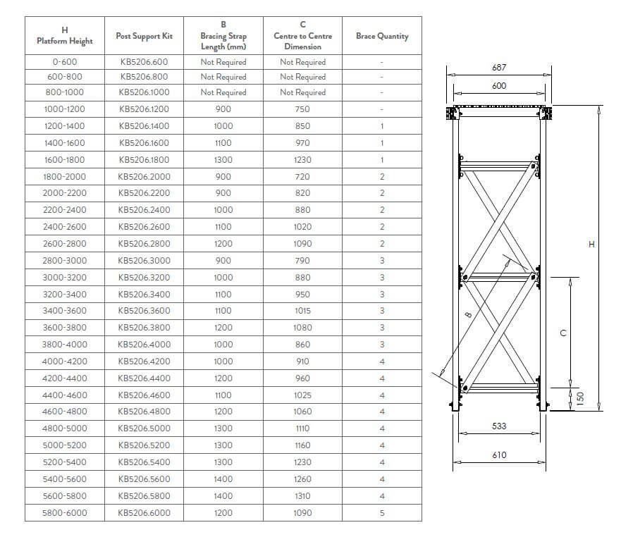
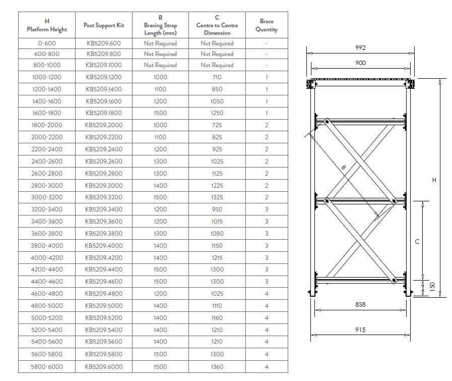
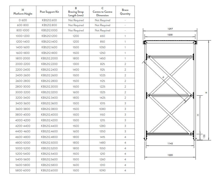
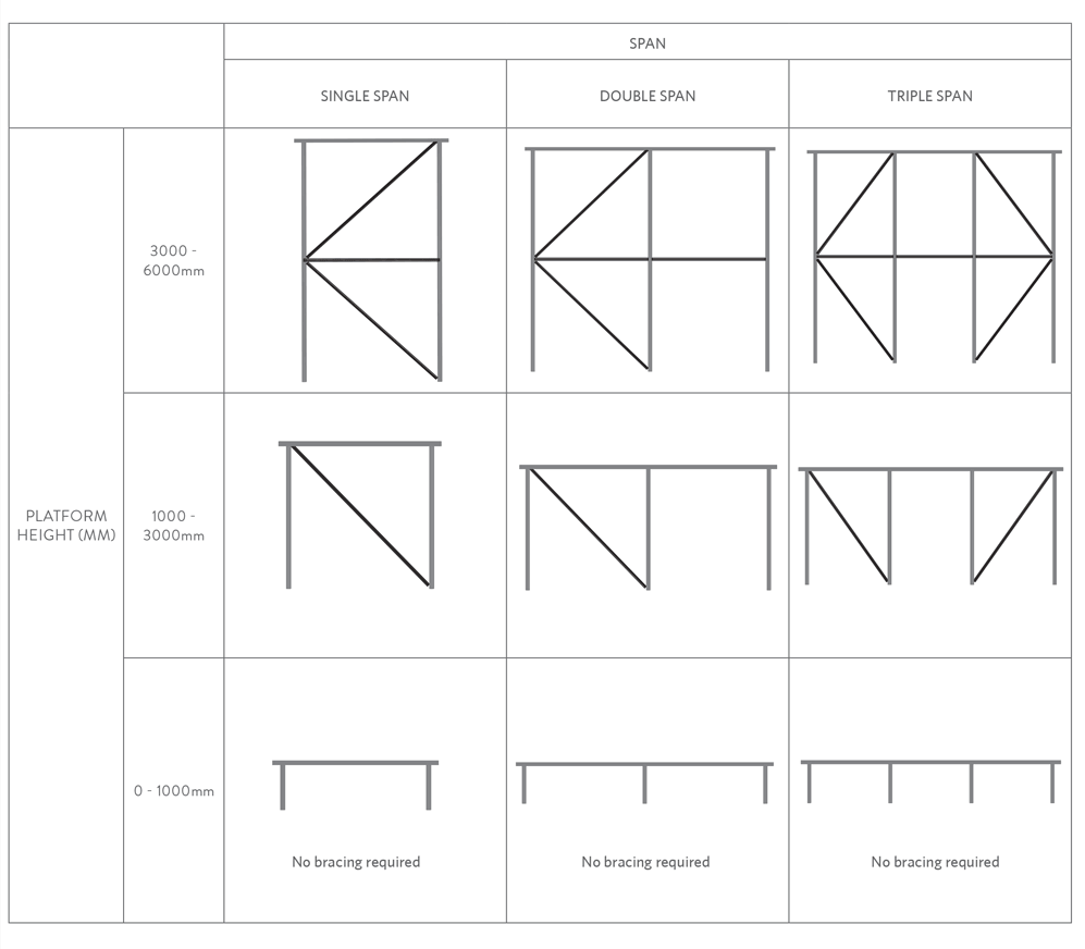
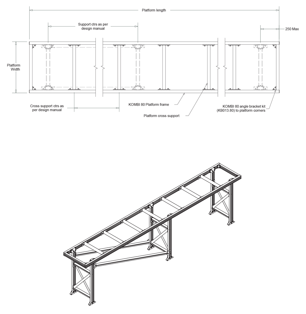
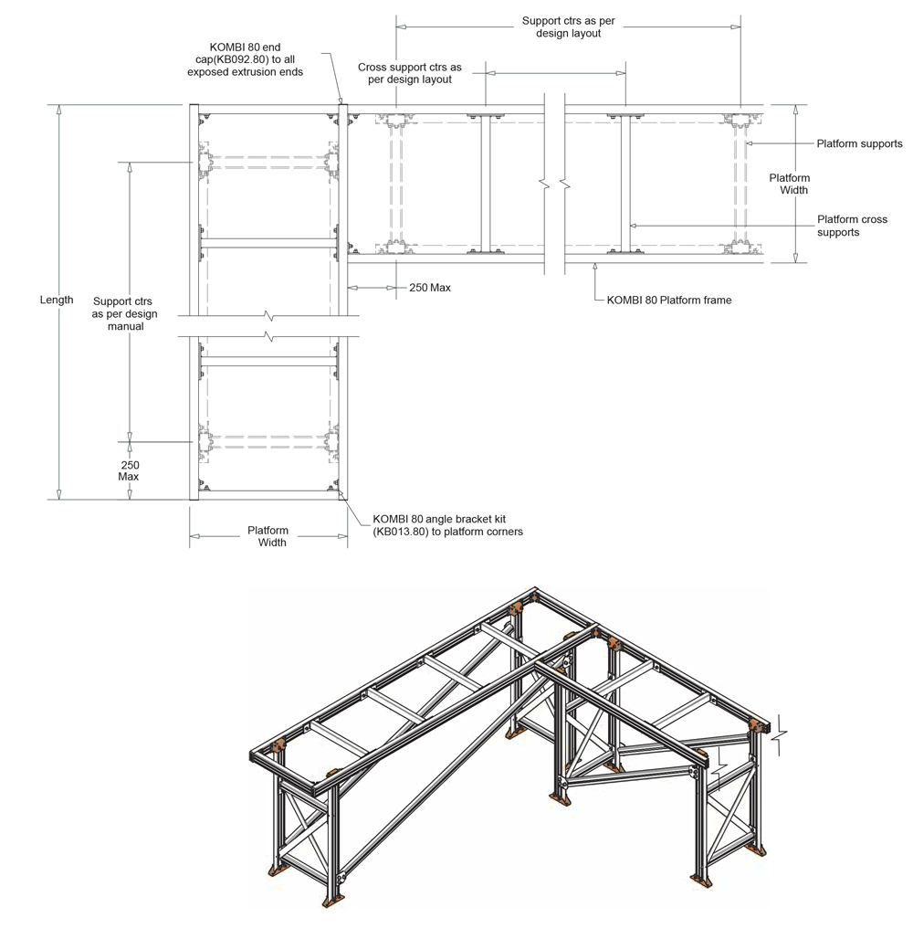
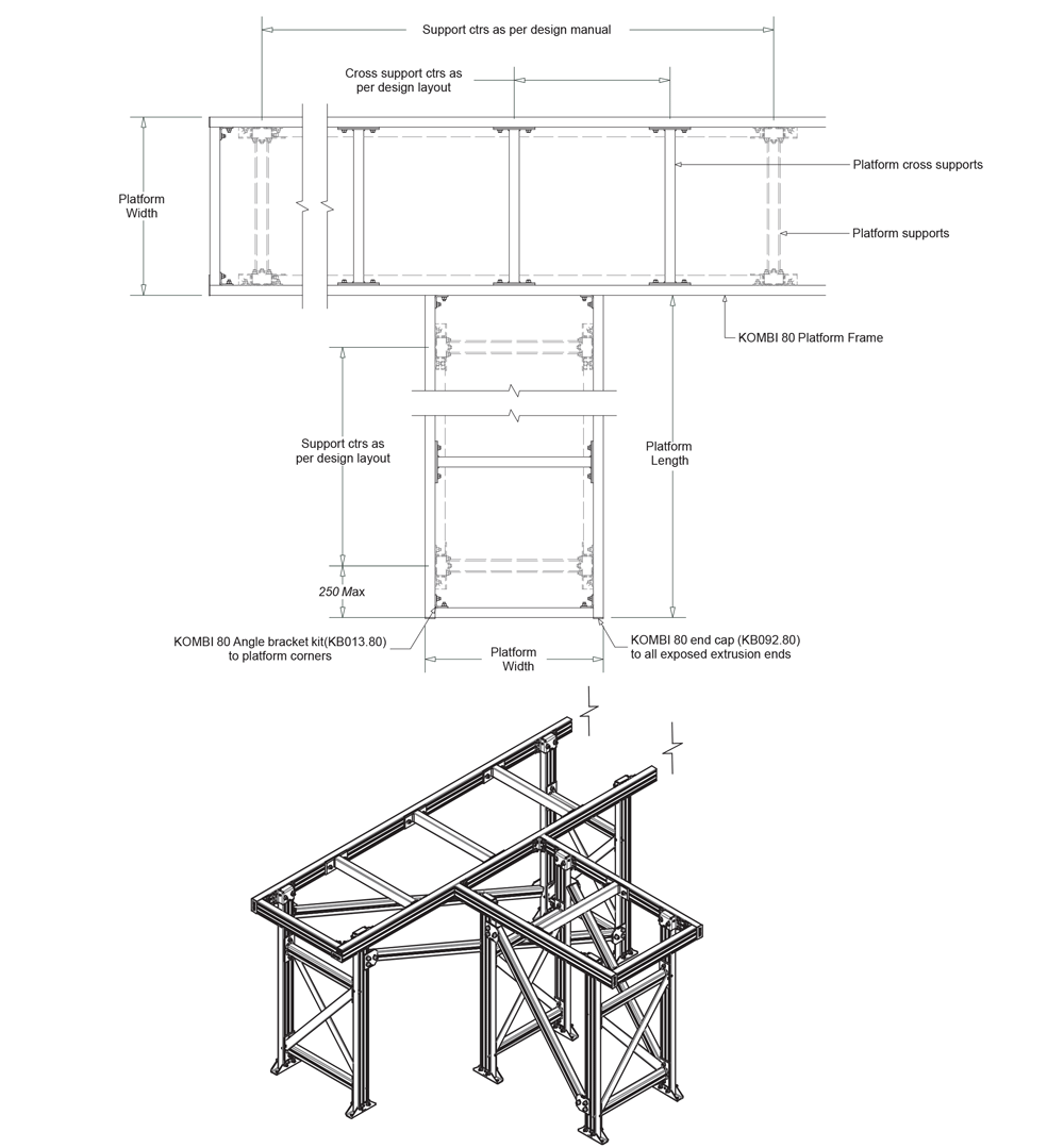
 Lateral Brace Installation
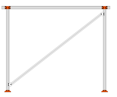 Lateral Brace Installation